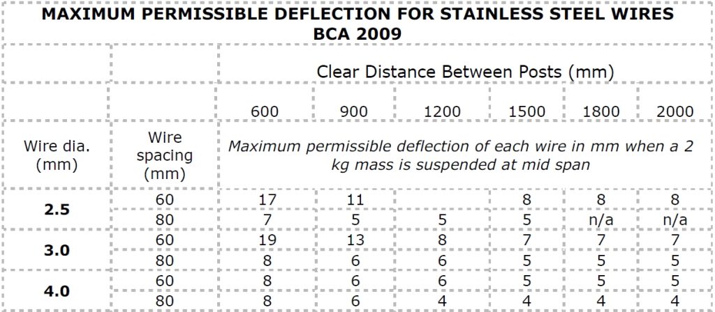
Maximum Permissible Deflection for Stainless Steel Wire Balustrades, BCA 2009
Wire Balustrade Deflection Table
Where a change of direction is made in a run of wire the 2 kg mass must be placed at the middle of the longest span.
If a 3.2 mm wire is used, the deflection figures for 3.0 mm wire are applied.
This table may also be used for a set of non-continuous (single) vertical wires forming a balustrade using the appropriate clear distance between posts as the vertical clear distance between the rails. The deflection (offset) is measured by hooking a standard spring scale to the mid span of each wire and pulling it horizontally until a force of 19.6N is applied.
n/a = Not allowed because the required tension would exceed the safe load of the wire.
This table has been limited to 60 mm and 80 mm spaces for 2.5 mm, 3 mm and 4 mm diameter wires because the required wire tensions at greater spacing would require the tension to be beyond the wire safe load limit, or the allowed deflection would be impractical to measure.