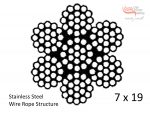
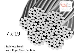
7×19 Stainless Steel Wire Rope G316 Specifications is a table outlining the Minimum Breaking Strain of 7×19 G316 Stainless Steel Wire Rope. Minimum Breaking Strain (MBS) is also known as the Minimum Breaking Load (MBL). In calculating the MRC, the load is applied along the length of the wire. If the load is applied perpendicular to the wire, the MRC is divided by a factor of 2.

The Minimum Breaking Strain is the stated minimum ‘strength’ of the wire rope. This load represents a mass or force that is required to make the wire rope fail or yield, also known as the Minimum Breaking Load (MBL). SWL or WLL are calculated by dividing the MBL by a safety factor (SF).
The Safe Working Load (SWL) is a common but outdated term (See “What is the Safe Working Load SWL?” post in our Advice section). The currently correct term is the Working Load Limit or WLL. SWL or WLL are calculated by dividing the MBL by a safety factor (SF) and the SF varies by application or project. Often it will be specified by the design engineer.
Low Cost Wire recommends a 10x SF if the lifting element (wire in this case) holds an object above ‘people’ and a 5x SF if the object is above ‘things’ and could never injure a person in the event of a catastrophic failure. The table below presents the WWL of the wire with a 10x SF when the suspended weight is held by wire in a Vertical Orientation or in a Horizontal Orientation.
Please NOTE: The dimensions and specifications of our products that we quote on this page and on every other page on this website are intended to be used for reference only. If product dimensions or specifications are critical to your application, please contact us for assistance.
If load specification is critical, Low Cost Wire recommend that you confirm all relevant details before ordering as information may change without prior notice.
Diameter |
MBS* (kN) |
MBS (kg) (approx) |
WLL (kg) (vertical) |
WLL (kg) (horizontal) |
|---|---|---|---|---|
| 1.2mm (3/64″) | 0.81 | 82.6 | 8.2 | 4.1 |
| 1.6mm (1/16″) | 1.10 | 112.2 | 11.2 | 5.6 |
| 1.8mm (7/128″) | 1.50 | 152.9 | 15.3 | 7.6 |
| 2.0mm (5/64″) | 2.00 | 203.9 | 20.3 | 10.1 |
| 2.5mm (3/32″) | 3.10 | 316.1 | 31.6 | 15.8 |
| 3.0mm | 6.90 | 703.6 | 70.3 | 35.1 |
| 3.2mm(1/8″) | 6.90 | 703.6 | 70.3 | 35.1 |
| 4.0mm (5/32″) | 8.60 | 876.9 | 87.7 | 43.8 |
| 5.0mm (3/16″) | 13.40 | 1366.4 | 136.6 | 68.3 |
| 6.0mm | 21.00 | 2150.0 | 215.0 | 107.5 |
| 6.4mm (1/4″) | 24.00 | 2447.3 | 244.7 | 122.3 |
| 8.0mm (5/16″) | 33.00 | 3365.1 | 336.5 | 168.2 |
| 10.0mm | 50.07 | 5106.0 | 510.6 | 255.3 |
| 12.0mm | 72.08 | 7350.0 | 735.0 | 362.5 |
| 14.0mm | 114.66 | 11692.0 | 1169.2 | 584.2 |
| 16.0mm (5/8″) | 141.80 | 14460.0 | 1446.0 | 723.0 |
